Contents

TELEMETRY
User manualAcquisition unit V3 & V3 Pro
Contents
TELEMETRY- 01Quick startYour first run
- 02What's in the box?Unpacking check
- 03Kit configurationsHow many suspension sensors · Which stroke
- 04Acquisition unitV3 and V3 Pro
- 05SensorsLinear sensors · GPS antenna · Brake and speed sensors
- 06MountingsFrame mountings · GPS mounting · Suspension mountings
- 07InstallationSuspension sensors · Digital brake sensors · Analog brake sensors · Speed sensor · GPS antenna · Acquisition unit
- 08IMU orientationAcquisition unit IMU orientation · IMU calibration
- 09Connecting the sensorsBefore you connect
- 10Connecting to your unitConnect to your BYB Telemetry
- 11Using the unitButtons and LEDs · Connectors · Connectors and channel mapping · BYB modes · Device configuration · Automatic sensor calibration · Hardware sensor calibration (expert users only) · Auto pause
- 12V3 Pro featuresLive data · BLE sensors — heart rate and power meter · BYB Chrono external triggers · Trigger placement on the track
- 13Riders, vehicles and setupsRider, vehicle, device · Vehicle and rider configuration · Setup history · How runs find their vehicle · When you change something mid-session · Fixing a run afterwards
- 14Download runs and manage configurationsThe Device panel
- 15Firmware updateUpdating the firmware
- 16Charging the systemBattery charging
- 17Cleaning the systemSystem cleaning
- 18TroubleshootingThe unit will not get a GPS fix · The run has no GPS map · The unit is not responding · The Wi-Fi password is not accepted · The unit does not appear in the Wi-Fi list · A channel reads zero or a flat line · The suspension data looks wrong or clipped · A run is missing, or the software will not load it · No brake or speed signal · The battery does not last a session
- 19SpecificationsAcquisition and memory
Quick start
Your first run
- Mount the system.Use the included mountings to install the acquisition unit and the sensors.Full steps in Installation.
- Create your rider profile in the software or app.Everything you record is filed under a profile: the runs, the vehicles and their setup history.Full steps in Rider, vehicle, device.
- Add your vehicle to the Garage.Enter brand and model, then the geometry: suspension travel, sensor travel, rear wheel travel and wheel size (mandatory values needed for stroke calculation).Full steps in Vehicle and rider configuration.
- Send the vehicle to the unit.Hold the run button for 2 seconds to enable Wi-Fi, then connect to the network BYB-Telemetry with the default password bybtelemetry.Send the configuration from the device panel, so every run is imported automatically under the right profile and vehicle.Full steps in Connecting to your unit.
- Power on and wait for the GPS fix.Press the power button once and wait for the run LED to switch on — the system is ready.Wait for the run LED to turn solid green: the GPS has a fix.
- Record.Press the run button once; the run LED blinks slowly while recording.Press it again to stop.
- Download the run.Hold the run button for 2 seconds to enable Wi-Fi and connect to BYB-Telemetry again — same default password, bybtelemetry.Open the software or app to download your runs and manage configurations.Full steps in The Device panel.
- Optional — add an external trigger or BLE sensors from the app, and set up the advanced features.
What's in the box?
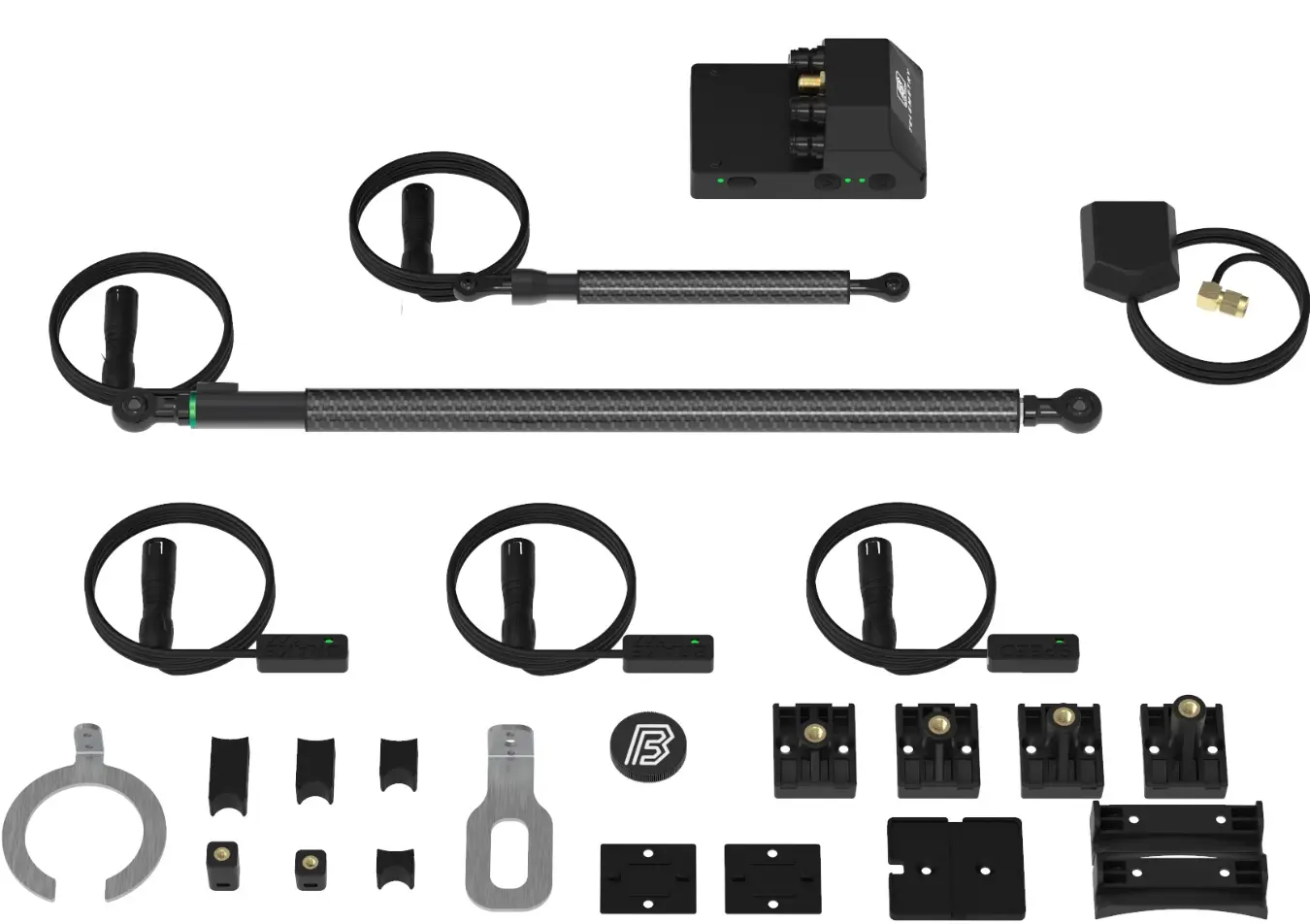
One acquisition unit, the sensors, and the parts that hold them on the vehicle.
Unpacking check
BYB Telemetry is a complete, ready-to-use data acquisition system for high-performance applications. Every kit is built from the same parts: the same acquisition unit, the same sensor bodies, the same software. What changes from one kit to the next is how many and which sensors it carries — set out in Kit configurations.
| Qty | Item | What it does |
|---|---|---|
| 1 | Acquisition unit | Records every channel and stores the runs |
| 2–4 | Suspension sensors | Measure suspension movement — stroke matched to the suspension |
| 1 | GPS antenna and mount | Position, speed and track mapping |
| 1 | Speed sensor | Wheel speedV3 Pro |
| 2 | Brake sensors, digital | Brakes usageV3 Pro |
| 2 | Acquisition unit mountings | Hold the unit on the frame or chassis |
| 1 | Suspension mounting kit | Steel and plastic brackets for one suspension sensor |
| 1 | Screw kit | Fixings for the mountings |
| 1 | Magnet kit | Magnets for the brake and speed sensorsV3 Pro |
| 1 | Connector caps kit | Seal the connectors you are not using |
Kit configurations
One system, four configurations. They differ mainly in the package content, and in the stroke of those sensors.
How many suspension sensors
Which configuration you need depends on how many suspensions the vehicle has. Two suspensions — one front, one rear — is the base configuration; each additional suspension adds one sensor and one mounting kit. Everything else in the kit stays the same.
| Configuration | Suspension sensors | What is measured | Vehicle mode |
|---|---|---|---|
| Base | 2 | Front suspension, rear suspension | MTB · MOTO |
| Base + 1 | 3 | Front left and right, rear | QUAD |
| Base + 2 | 4 | Front left and right, rear left and right | CAR |
| Custom | On request | Any combination, including non-BYB sensors | OPEN |
The V3 has two sensor connectors and therefore covers the base configuration only. Three or four suspension sensors, or any extra sensor — brakes, speed, remote accelerometers — require a V3 Pro.
Which stroke
Choose the sensor stroke from the travel of the suspension it measures, not from the vehicle it is fitted to. Four standard strokes cover almost every vehicle; anything else is made to order.
| Sensor | Standard strokes | Suits suspension travel up to | Body diameter |
|---|---|---|---|
| Long | 210 mm · 350 mm | up to 210 mm · 350 mm | 13 mm |
| Short | 80 mm · 150 mm | up to 80 mm · 150 mm | 9.5 mm |
Acquisition unit
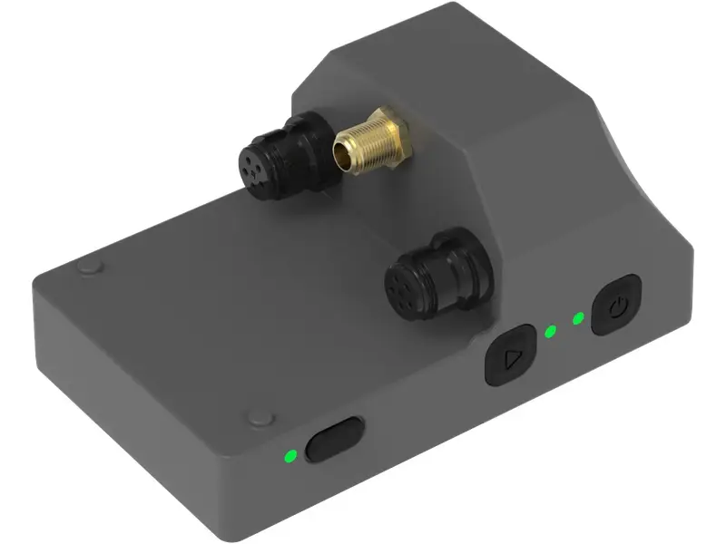
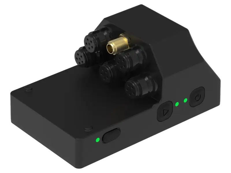
Two versions: V3 and V3 Pro. Some features differ.
V3 and V3 Pro
Both units record suspension movement and vehicle dynamics with a built-in IMU (3-axis accelerometer and 3-axis gyroscope), store runs on internal memory and transfer them over Wi-Fi. The V3 Pro adds more connectors, configurable channels and the features that depend on them.
| V3 | V3 Pro | |
|---|---|---|
| Sensor connectors | 2 | 5 |
| GPS connector (SMA) | 1 | 1 |
| Channel mapping | Fixed | User-defined |
| Vehicle modes | MTB, MOTO | MTB, MOTO, QUAD, CAR, OPEN |
| Built-in IMU (6-axis) | Yes | Yes |
| Built-in GPS, 25 Hz multi-constellation | Yes | Yes |
| Sampling rate per channel | 500 Hz fixed | 500 – 1000 Hz, selectable |
| Suspension linear sensors | 2 | 4 |
| Speed sensor | — | Yes |
| Brake sensors | — | Yes |
| Wired trigger | — | Yes |
| External 100 g accelerometers | — | Yes |
| External 200 g accelerometers | — | Yes |
| Strain gauge sensors | — | Yes |
| Steering sensor | — | Yes |
| Custom 3.3 V sensors | — | Yes, in OPEN mode |
| BLE heart rate and power meter | — | Yes |
| BYB Chrono external triggers | — | Yes |
| Sensor calibration, manual | — | Yes |
| IMU calibration | — | Yes |
Sensors
Universal linear sensors and the parts that complete the system.
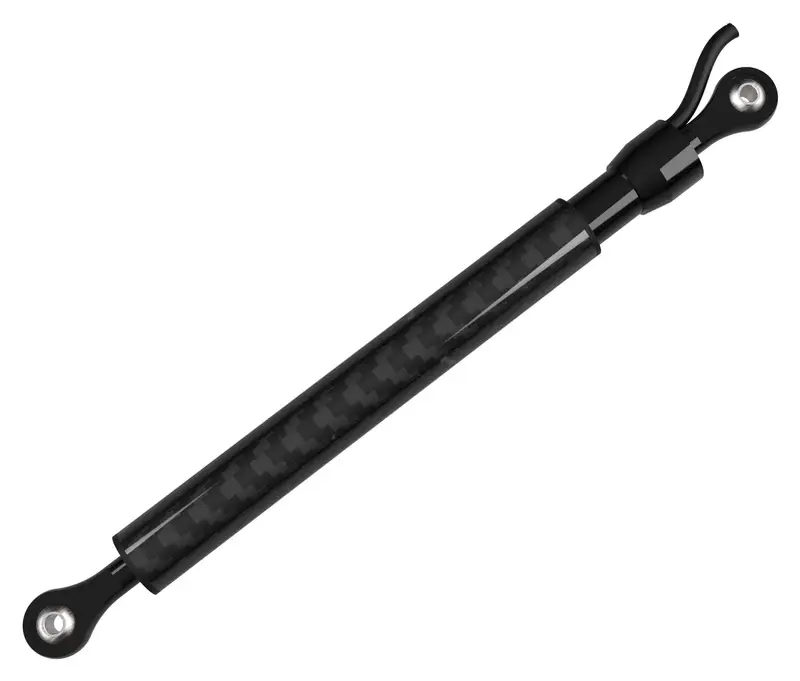
Linear sensors
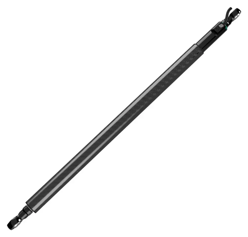
What a sensor has to match is the suspension it measures — its travel, and the space around it. The only difference from one sensor to the next is stroke and body diameter; the strokes and the kits built from them are in Kit configurations.
- High-precision motorsport sensor
- Compact black anodised aluminium body
- Low actuation force
- Self-aligning rod-end joints (removable)
- Sealed against water and dust
- Carbon cover
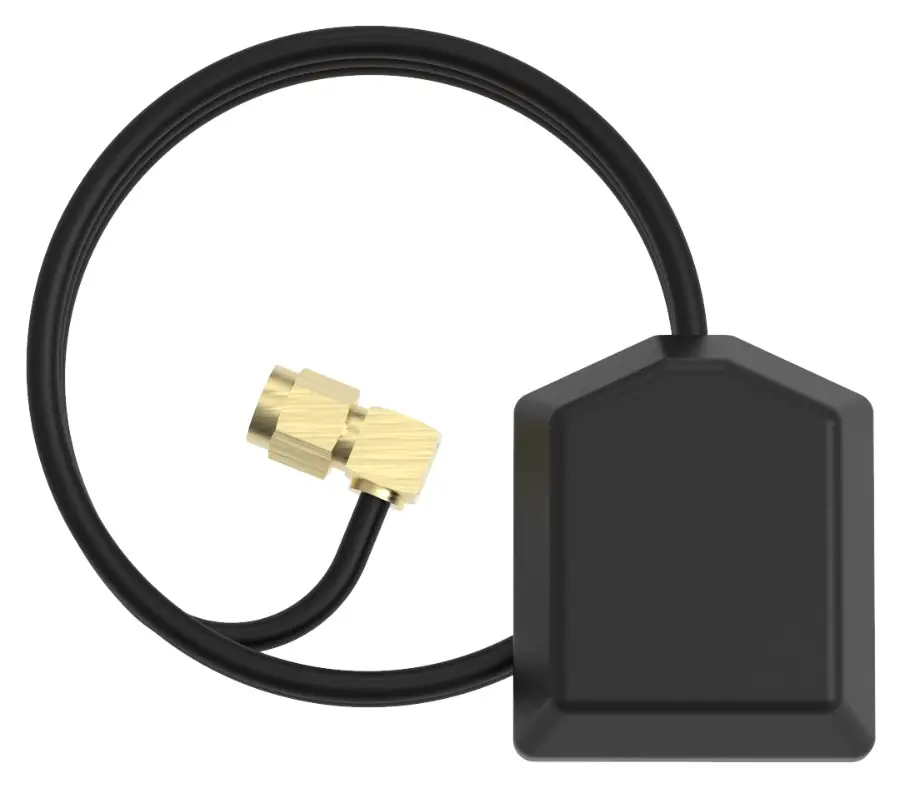
GPS antenna
The GPS antenna records position, speed over ground and the shape of the track, and is the same part in every configuration. It is what places your data on the map, so a channel trace can be read against the section of track that produced it.
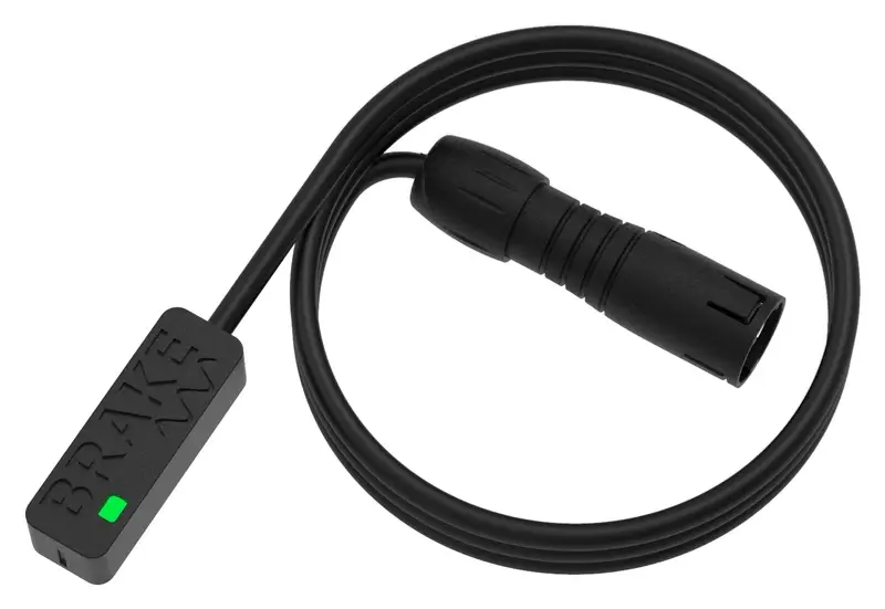
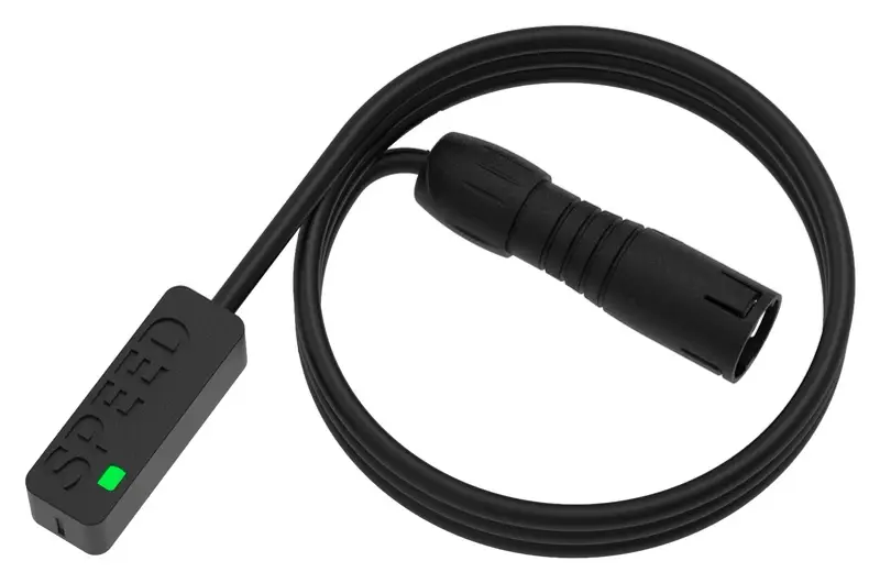
Brake and speed sensors
V3 Pro onlyBrake and speed data unlock features in the software and app — you can see how the rider brakes, and find the exact sections of track where time is won or lost. Both sensors read a magnet, so nothing hydraulic is opened and nothing is spliced.
- Compact
- Digital output; an analog version is available as an upgrade
- Fast to fit — the brake sensors do not require opening the hydraulic circuit
Mountings
Where each part goes, and what holds it there.
Frame mountings
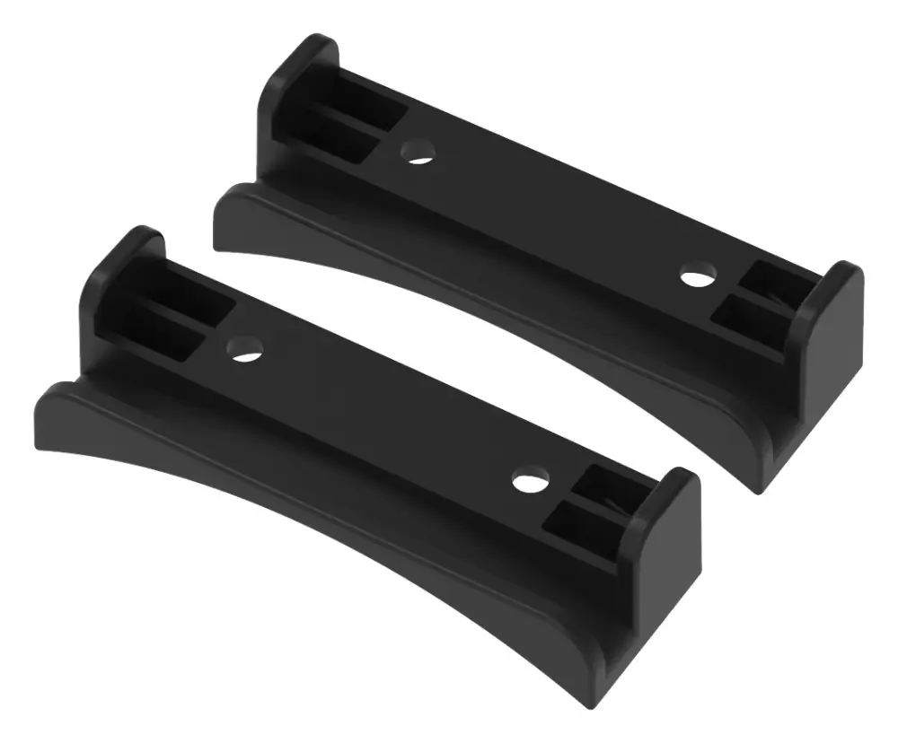
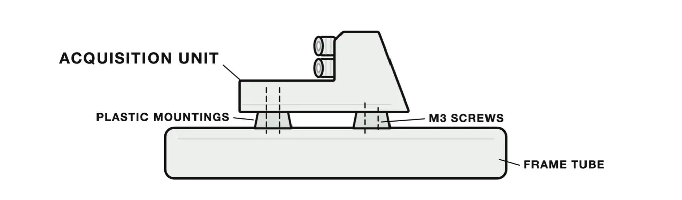
The acquisition unit ships with a set of plastic mountings for a frame or chassis tube. It can also be mounted anywhere on the vehicle through the four M3 threaded holes underneath the unit. Custom mountings can be 3D printed on request.
GPS mounting
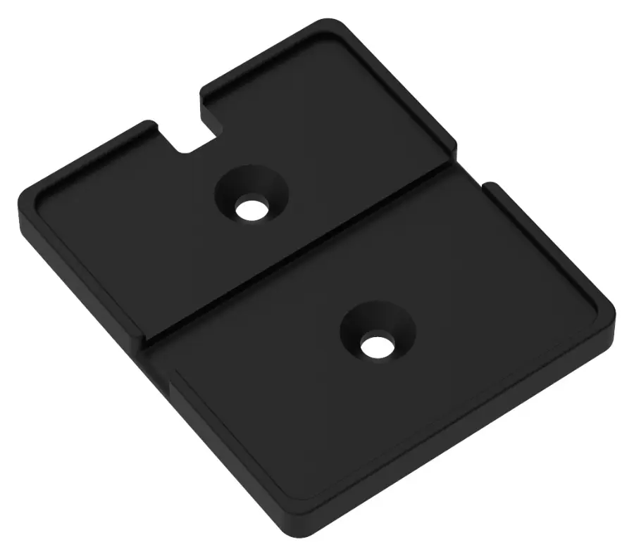
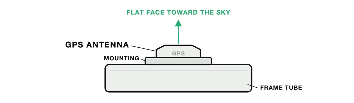
The GPS antenna mounts with a single cable tie. Install it where it has a clear view of the sky.
Suspension mountings
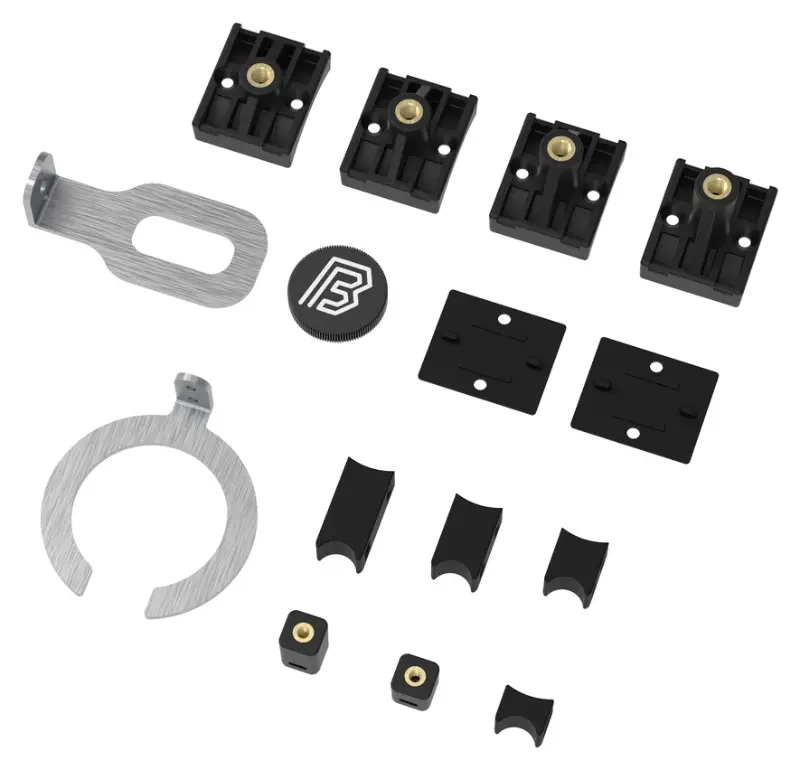
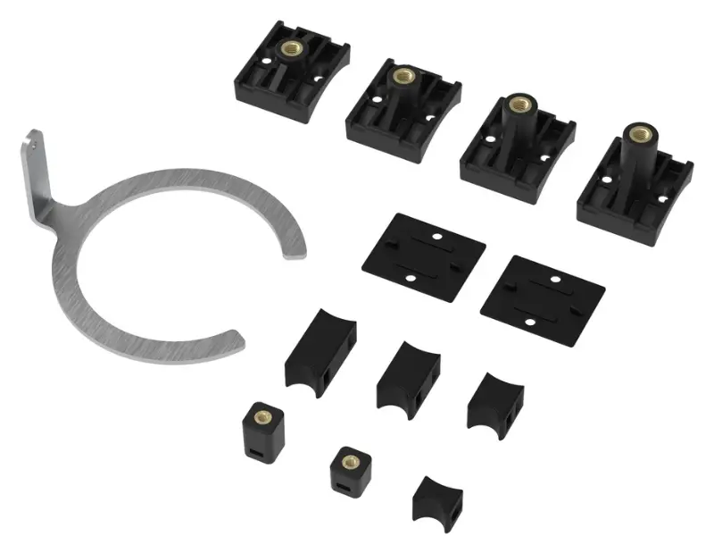
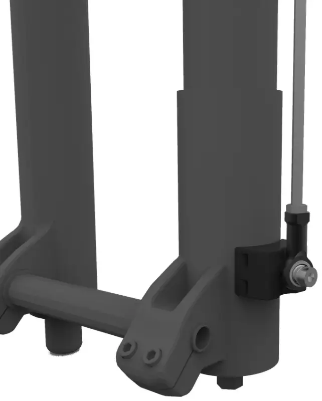
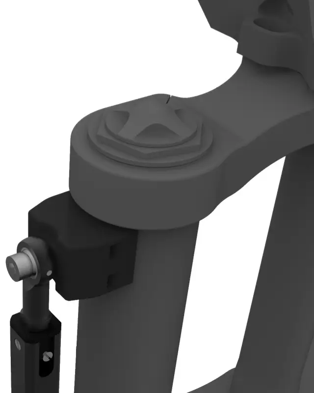
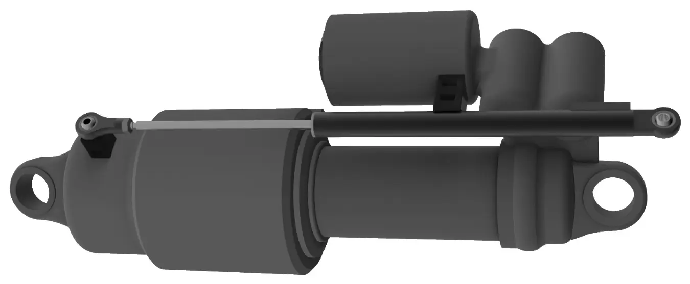
The suspension sensors install with a complete set of steel and plastic mountings, compatible with every suspension type: double crown, single crown, air or spring. Two of the available sets are shown below.
Installation
Suspension sensors
Each suspension sensor spans the moving and the fixed part of one suspension, held by a bracket at each end. Fit one sensor at a time.
- Check the sensor stroke covers the full travel of the suspension it will measure.A sensor shorter than the travel is destroyed by the first hard hit — see Kit configurations.
- Choose a position where the sensor runs clear of the tyre, the linkage and anything that could strike it.
- Fit one bracket to the moving part and one to the fixed part, using the mounting kit for that suspension.
- Attach the sensor to both brackets through the self-aligning joints.In tight spaces, remove the upper rod-end joint and its grub screw to get the sensor in.
- Set the sensor slightly retracted — 2 to 3 mm from fully extended — before you tighten anything.Never fit a sensor fully extended.
- Cycle the suspension by hand through its full travel.The shaft must slide freely, without force and without twisting.The sensor must not reach the end of its own stroke before the suspension reaches the end of its travel.The carbon cover must not touch the frame, the chassis or the mountings.
- Fit the carbon cover if it was removed, and calibrate it — see Automatic sensor calibration.
Digital brake sensors
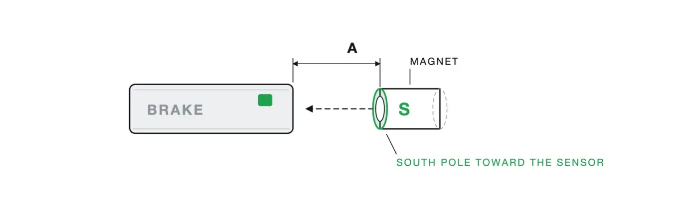
V3 Pro onlyThe sensor reads a magnet on the brake lever. The sensing element sits at the end of the sensor opposite the cable, so that end is what the magnet must face.
- Fit the sensor beside the brake lever with a thin cable tie, where it cannot interfere with the rider.Do not overtighten the cable tie — it may damage the sensor.
- Fit the magnet to the lever with its south pole toward the sensor, so that it meets the end of the sensor face-on, sharing one axis with it.Never the cable end, never the flank of the body.The magnet carries no pole marking: with the unit on and the sensor connected, the correct side is the one that lights the sensor LED. If it stays off, turn the magnet 180° and refit.
- Set the gap as small as the lever travel allows, without the magnet touching the sensor.With the lever released the LED is off; pulling the lever turns it on.
Analog brake sensors
V3 Pro onlyThe analog sensors mount exactly like the digital ones and add an automatic calibration routine, so they report how hard the lever is pulled rather than only whether it is.
- Fit sensor and magnet as for the digital sensors: beside the lever with a thin cable tie, the magnet south pole toward the sensor, facing the end opposite the cable and sharing one axis with it.Do not overtighten the cable tie — it may damage the sensor.The magnet carries no pole marking: with the unit on and the sensor connected, the correct side is the one that lights the sensor LED. If it stays dark through the whole lever travel, turn the magnet 180° and refit.
- Set the gap as small as the lever travel allows, without the magnet touching the sensor.Correct installation: with the lever fully extended the LED is off, and it brightens gradually through the travel to full brightness with the lever fully pulled.
Speed sensor
V3 Pro onlyThe speed sensor reads a magnet fitted to the wheel, once per revolution.
- Fit the sensor with a cable tie to a fixed part of the suspension or chassis, close to the wheel.Do not overtighten the cable tie.
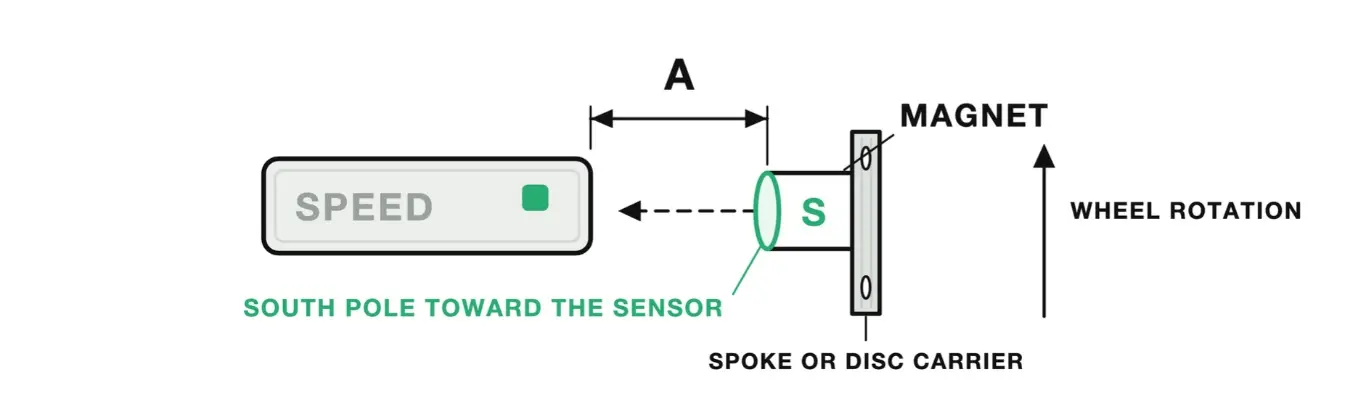
- Fit the magnet to the wheel — spokes or disc carrier — with the south pole facing the sensor head.
- Set both sensor and magnet as close to the hub as the parts allow, and the gap between them as small as possible.
- Check detection before riding: with the unit powered on, turn the wheel.The sensor LED must light up each time the magnet passes. If it does not, close the gap or turn the magnet over.
GPS antenna
Install the GPS antenna with the dedicated mount and a couple of cable ties, as high on the vehicle as you can and clear of obstructions — a top tube, a tank bracket or a roof surface all work.
Acquisition unit
Install the acquisition unit on the frame or chassis with the supplied plastic mountings, or design your own around the four M3 threaded holes on the bottom of the unit.
IMU orientation
How to read the acceleration and gyroscope data.
Acquisition unit IMU orientation
The acquisition unit contains a 3-axis accelerometer and a 3-axis gyroscope. All acceleration and gyroscope channels appear in the software and follow the orientation shown below.
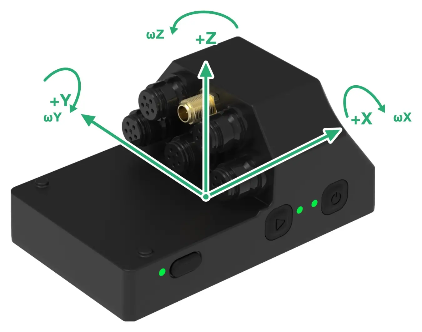
The axes belong to the unit, not to the vehicle. Mount the unit at any angle and calibrate: from then on the software rotates the readings so X, Y and Z line up with the vehicle instead of with the box.
IMU calibration
V3 Pro onlyIMU calibration teaches the system how the unit sits on the vehicle. It measures gravity in the unit's own axes while the vehicle stands still, works out the rotation between the two, and stores it. When you open a run, that rotation is applied to every acceleration and gyroscope channel, so the axes read as vehicle axes whatever angle the unit is mounted at.
This is why no bespoke mounting is needed. The unit does not have to sit level, square to the vehicle, or with Z pointing straight up — fit it wherever it is protected and out of the way, then calibrate.
- Fit the unit in its final position and tighten the mounting.Any angle is allowed. Calibration is only valid for the position it was measured in.
- Stand the vehicle on level ground as it sits when ridden, and leave it still.Hold it upright rather than leaning it: the calibration records the current position at the moment the calibration button is presses.
- Press IMU calibration in the software or app.It takes a moment and needs no movement — the vehicle must not be rocked or pushed.
- Choose whether Z reads positive up or positive down.A software setting, changeable at any time. Pick the convention your data analysis expects.
Connecting the sensors
One colour per channel, on the unit and in the software.
Before you connect
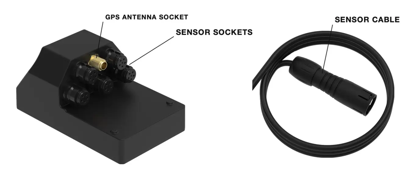
The acquisition unit has one GPS connector and either 2 or 5 sensor connectors. BYB Telemetry follows a fixed colour scheme, used on the connectors and inside the software and app alike. The channel colours can be changed in the software settings if you prefer another scheme. Connect the sensors according to the selected mode. Each connector has a colour and an assigned position — the layout for both units is in Using the unit.
Connecting to your unit
One Wi-Fi network. Everything else — configuration, downloads, firmware — goes through it.
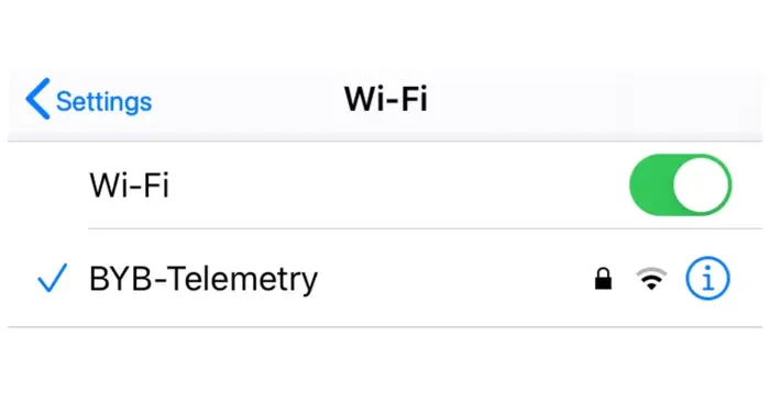
Connect to your BYB Telemetry
- Network name
- BYB-Telemetry
- Password
- bybtelemetry
- Hold the run button for 2 seconds. The run LED starts blinking blue rapidly.
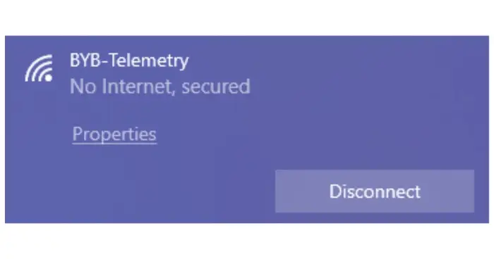
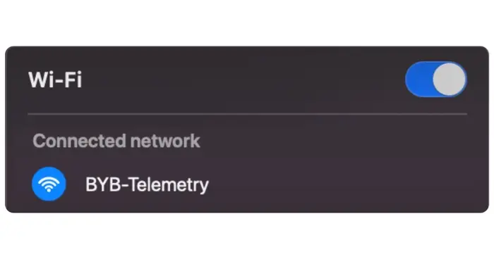
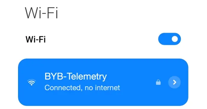
- On your phone or computer, look for the Wi-Fi network BYB-Telemetry in the list.
- Connect using the password above — all lower case, one word, no spaces.
- Your device may report "Connected" or "Connected without internet" — both are normal.
Using the unit
Buttons, LEDs, connectors and settings.
Buttons and LEDs
The unit has two buttons — power and run — and everything is done with a press or a hold. Both buttons and all three LEDs are on the side face, in the same places on either unit.
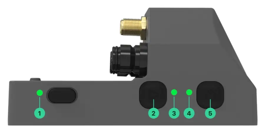
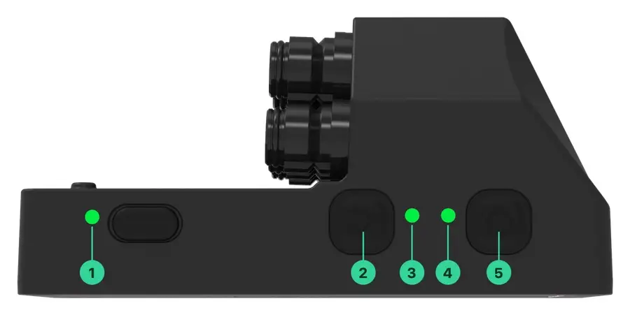
| Control | What it is | |
|---|---|---|
| 1 | Charge LED | Lights while the battery is charging, beside the charging port. |
| 2 | Run button | Starts and stops an acquisition, and enables connection mode. |
| 3 | Run LED | The state of the acquisition. |
| 4 | Power LED | The state of the unit. |
| 5 | Power button | Switches the unit on and off. |
| Button | Action | What happens |
|---|---|---|
| Power | Press once | Switches on; press again to switch off. |
| Run | Press once | Starts an acquisition; press again to stop. |
| Run | Hold 2 s | Enables connection mode (Wi-Fi); press again to disable. |
| Power | Hold 4 s | USB data transfer mode — the unit appears as a drive.V3 Pro |
| Power | Hold 8 s | Factory reset — restores the default settings. |
| Power | Hold 15 s | Forces a restart. |
| LED | State | Meaning |
|---|---|---|
| Power | Green | Powered on, battery level OK. |
| Power | Red | Powered on, battery below 40%. Recharge before the next run. |
| Run | Red solid | Ready to acquire, GPS has no fix yet. |
| Run | Green solid | Ready to acquire, GPS fix acquired. |
| Run | Blinking slowly | Sampling data. |
| Run | Blinking slowly + blue flash | Sampling data with BLE sensors connected. The number of blue flashes matches the number of connected BLE sensors.V3 Pro |
| Run | Blinking fast, blue | Connection mode (Wi-Fi) is active. |
| Run | Blue solid, then blinks | At startup only: searching for saved BLE sensors.V3 Pro |
| Run + Power | Both blue solid | USB data transfer mode is active.V3 Pro |
| Charge | On | Battery charging. The LED goes off when the battery is full. |
Connectors
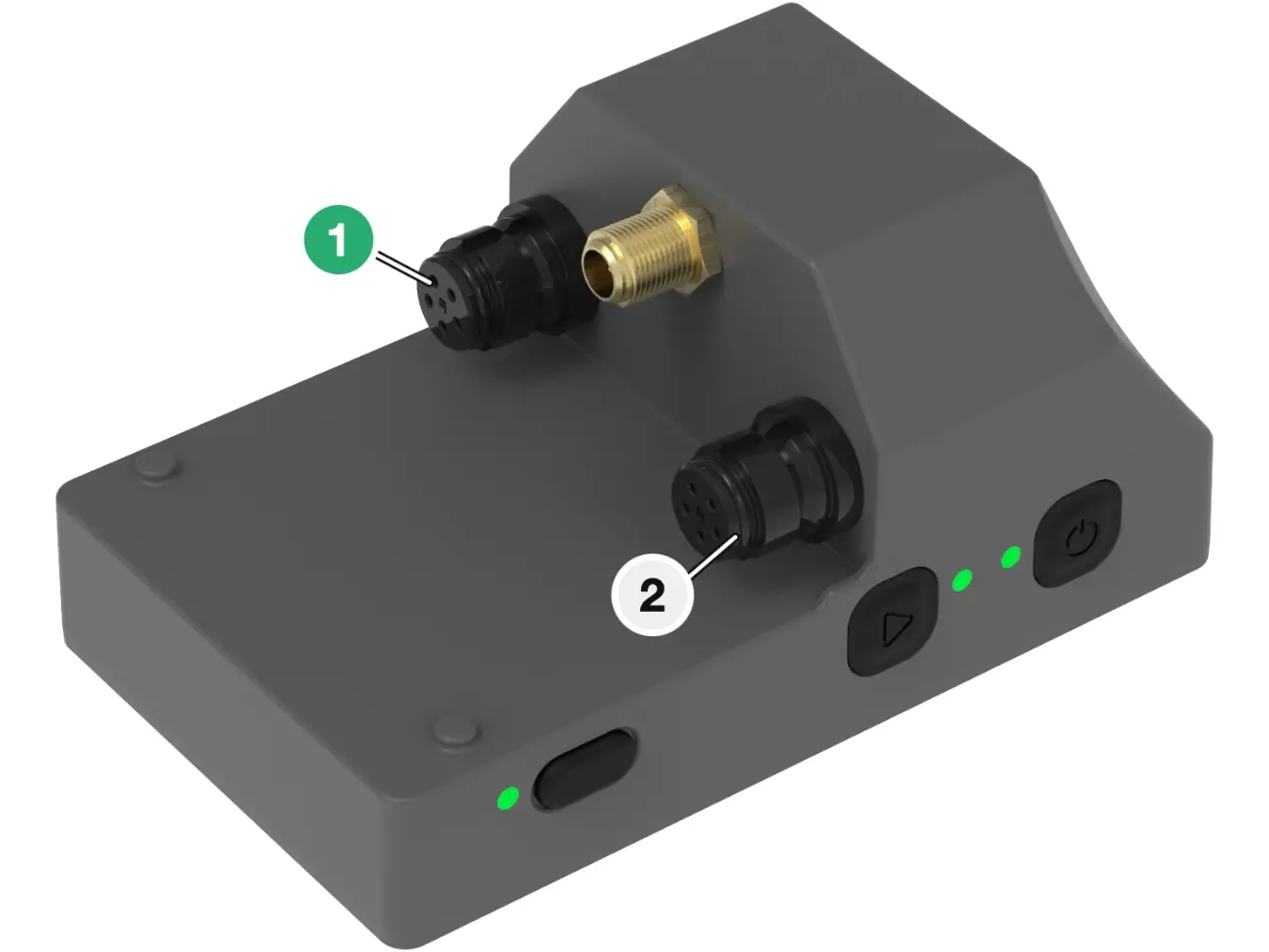
V3 onlyThe V3 has two sensor connectors and the GPS connector, so it carries two suspension sensors and the antenna. The mapping is fixed: connector 1 on the left, connector 2 on the right, GPS SMA in the middle.
| Connector | Sensor |
|---|---|
| 1 | Suspension 1 |
| 2 | Suspension 2 |
| SMA | GPS antenna |
Connectors and channel mapping
V3 Pro onlyThe V3 Pro has five sensor connectors and the GPS connector. The five are a shared pool, mapped as you need them: any combination of suspension, speed, brake and custom sensors, up to five in all. Each connector is numbered and dynamically mapped, so the unit follows your setup rather than the other way round.
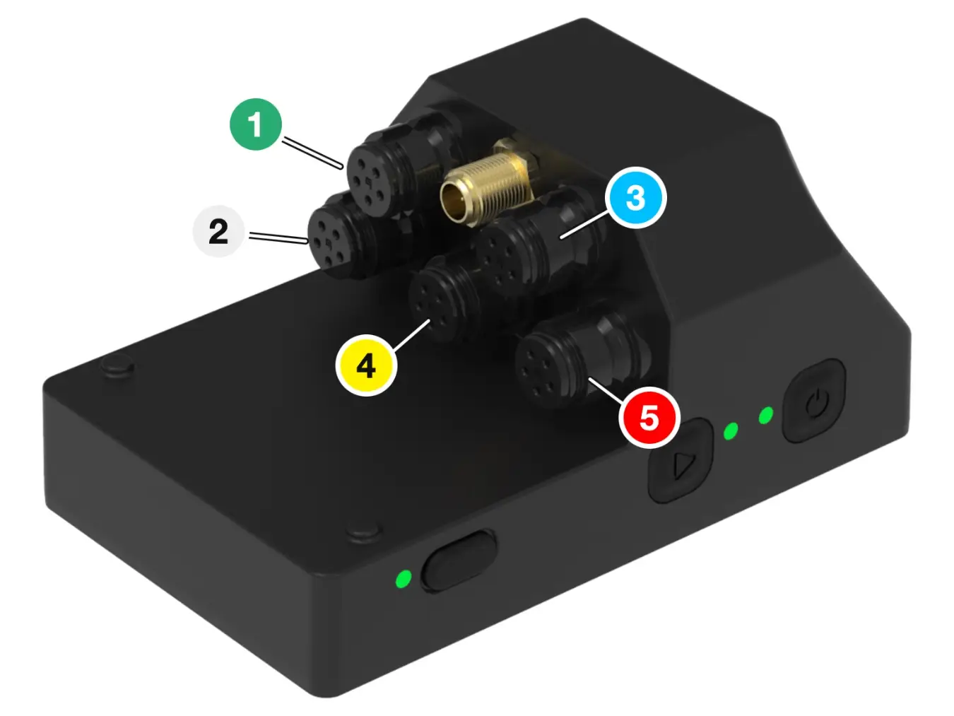
Standard configuration:
| Connector | Sensor |
|---|---|
| 1 | Suspension 1 |
| 2 | Suspension 2 |
| 3 | Speed sensor |
| 4 | Front brake |
| 5 | Rear brake |
| SMA | GPS antenna |
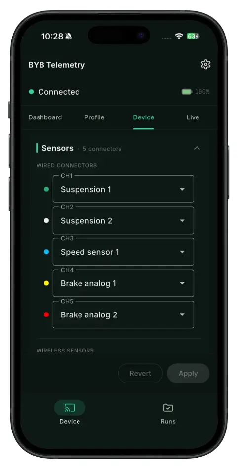
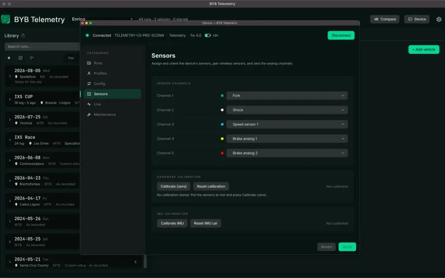
To change it, connect to the unit from the app or the PC software, open the device configuration and assign each connector to the sensor you have installed.
BYB modes
The mode tells the software and app which data to expect and which charts to build. Select it before you start an acquisition, and connect the sensors to match it.
| Mode | Suspension channels |
|---|---|
| MTB | Suspension 1 and 2 |
| MOTO | Suspension 1 and 2 |
| QUADV3 Pro | Front left and right suspension, rear suspension |
| CARV3 Pro | Front left and right suspension, rear left and right suspension |
| OPENV3 Pro | Custom sensors on CH1–CH5 |
Speed and brake channels are recorded alongside the suspension channels in every mode except OPEN, where you assign all five channels yourself.
OPEN mode is for custom sensors. All analog channels CH1 to CH5 are available and you do not declare what is connected — keeping track of that is your responsibility. Runs recorded in OPEN mode are saved as .bybOpen and can only be opened, and converted to .csv, with the BYB Telemetry software.
Device configuration
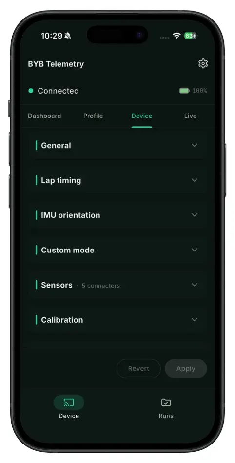
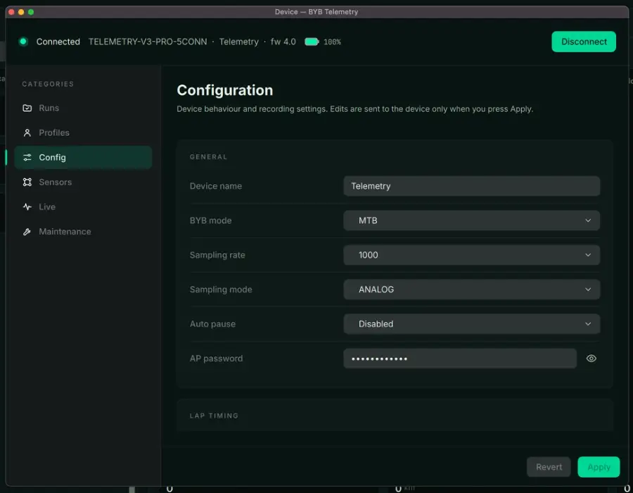
The settings below are read and written from the app or the PC software while the unit is connected over Wi-Fi. Edits reach the unit when you press Apply.
- Device name
- The name assigned to the device. In connection mode it becomes the Wi-Fi network name, e.g. BYB-DeviceName.
- BYB mode
- Selects the vehicle mode. Connect the sensors according to the mode you select — the modes are listed in BYB modes.
- Auto pause
- Stops data sampling when the vehicle is not moving. Conditions are in Auto pause.
- AP password
- The password of the device Wi-Fi network. Default: bybtelemetry.
- Sampling rateV3 Pro
- The acquisition rate of each channel.
- Channel mappingV3 Pro
- The assignment between each connector and its sensor. Fully customisable.
- Sensor calibrationV3 Pro
- Selects automatic or hardware calibration — see Sensor calibration.
- IMU calibrationV3 Pro
- Calibrates the built-in IMU — see IMU calibration.
- Lap typeV3 Pro
- Closed circuit (a loop with a shared start/finish) or open circuit (separate start and finish).
- External triggerV3 Pro
- Enables trigger reception and declares how many triggers are in use.
- External trigger IDV3 Pro
- The name of the trigger. It must match the ID of the trigger you are using.
- Heart rate sensorV3 Pro
- Enables the BLE heart rate sensor.
- Power meter sensorV3 Pro
- Enables the BLE cycling power meter.
- Heart rate / power meter pairingV3 Pro
- Starts the pairing procedure for a specific BLE sensor.
- Custom codeV3 Pro
- A code we assign to a customer for a dedicated feature. Leave it as it is unless we have given you one.
- Format SD
- Wipes every run stored in memory.
- Factory reset
- Returns the whole device to its factory configuration.
Automatic sensor calibration
RecommendedSuspension sensors need no calibration: the system detects the maximum and minimum value of each suspension channel by itself. For accurate measurements, follow these rules.
- Install the linear sensors slightly retracted — never fully extended. Always retract the sensor by 2–3 mm.
- Make sure each sensor has enough travel to cover the full travel of the suspension it measures.
- Check that the carbon cover cannot collide with the frame or any mounting hardware.
- Enter the correct values in millimetres — suspension travel, sensor travel, wheel size and rear travel — in the vehicle configuration (Bike Config) menu of the app or PC software.
- Capture at least one moment per run with the suspension fully extended — a jump, or simply lifting the vehicle before the run starts.
Hardware sensor calibration (expert users only)
V3 Pro onlyThe V3 Pro can also be calibrated at the unit. The procedure sets the minimum value of every sensor at once.
- Install the linear sensors slightly retracted — 2–3 mm from fully extended.
- Check that each sensor has enough travel to cover the full suspension travel.
- Check that the carbon cover cannot collide with the frame or the mountings.
- Enter the suspension travels, wheel size and rear travel in the vehicle configuration (Bike Config) menu.
- With every sensor installed and the vehicle raised so the suspension hangs fully extended, press Calibrate.The current readings become the new minimum calibration values, and the app and software calculate from them.
Auto pause
Auto pause stops sampling when the vehicle is not moving, so a run does not fill up with the time spent standing between runs.
| Setting | Sampling pauses when |
|---|---|
| Disabled | Never — the system samples until you stop it. |
| IMU | No movement is detected for 5 seconds. |
| GPS | GPS speed stays below 6 km/h for 5 seconds. |
| IMU + GPS | Both conditions are met at the same time. |
V3 Pro features
V3 PROLive data, BLE sensors and lap timing.
Live data
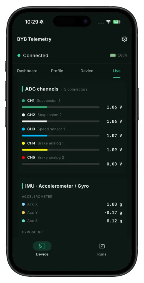
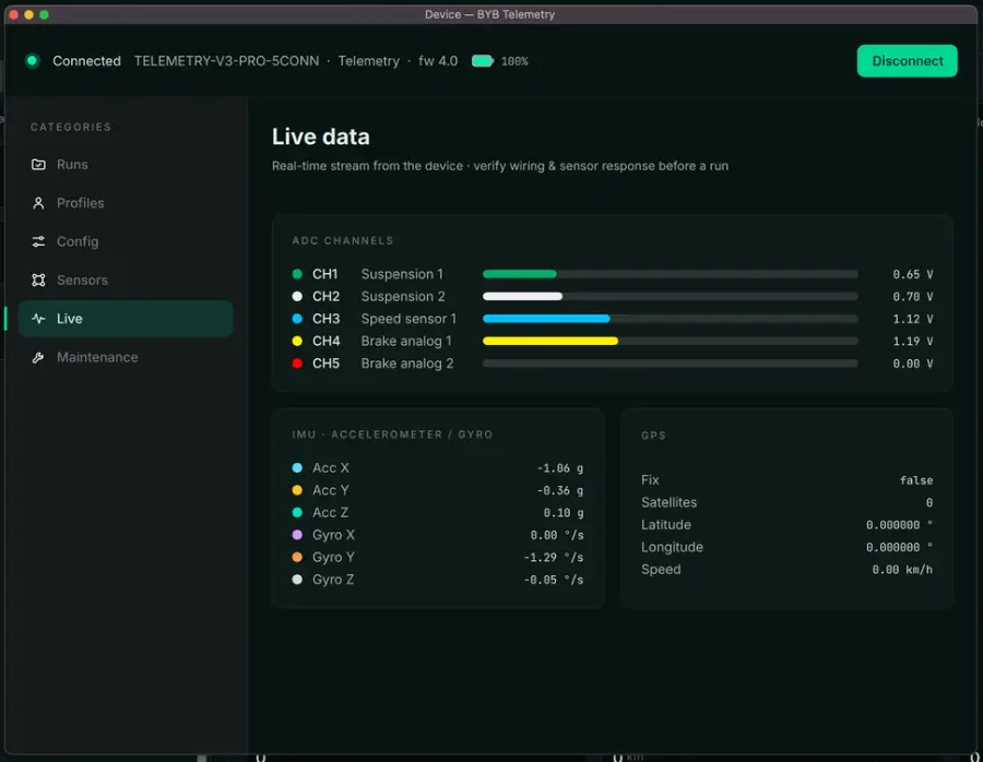
The Live page streams the sensor readings from the unit while it is connected: the analog channels with their voltage, the accelerometer and gyroscope, and the GPS fix. Use it before a run to check that every sensor is wired and responding — move a suspension, pull a brake lever, turn a wheel, and watch the value follow.
BLE sensors — heart rate and power meter
The V3 Pro connects to commercial BLE heart rate monitors and cycling power meters. Each sensor is paired once; its unique ID is then stored in the device for future sessions.
- Activate the sensor — wear the heart rate strap, or move the power meter.
- Enable Wi-Fi mode on the BYB Telemetry.
- Open the app or software and go to the device configuration menu.
- Tap Scan heart rate sensor or Scan cycling power meter.
- Wait for pairing to finish — the unique code of the paired sensor is displayed.
- Set Heart rate sensor or Power meter sensor to YES before starting a run.
BYB Chrono external triggers
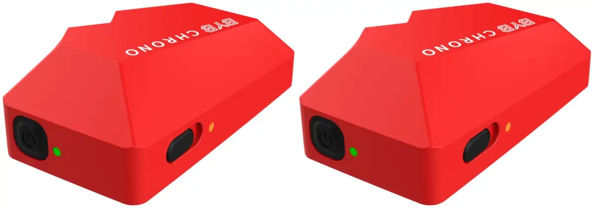
The V3 Pro records lap times from BYB Chrono external triggers placed along the track. Placement, pairing and the trigger’s own settings are in the BYB Chrono manual.
- Open lap
- The track has a distinct start and finish; entry and exit points are separate.
- Closed lap
- The track is a loop with a shared start/finish line. The entry and exit laps are automatically excluded from calculations.
- External trigger
- Pairs Chrono with a trigger for accurate timing independent of GPS reception. Enable reception and declare the number of triggers used.
- External trigger ID
- The trigger name. Every trigger in use must carry the same ID — four triggers on one track all share it, for example "Trigger-TeamX". Choose a name of your own so it is not shared with another team on the same track. Default: Chrono.
- On the acquisition unit, set Lap type to match the track (closed or open circuit), set External trigger to Yes, and enter the External trigger ID and the number of triggers you will use.
- Switch each trigger on and set its External trigger ID to the same name entered on the unit — all triggers in use carry one name, for example "Trigger-TeamX".
- Place the triggers along the track as described in Trigger placement on the track, switched on, and check that each LED is blinking: a blinking LED means the trigger is active.
| Action | What happens |
|---|---|
| Hold 8 s | Factory reset — restores the trigger to its default settings. |
| Hold 15 s | Forces a restart. |
Trigger placement on the track
Where the triggers sit decides whether the lap times are usable. A trigger too close to the start or the stop point fires while the vehicle is still stationary; two triggers too close together interfere with each other. Set the lap type first, then place the triggers to match it.
- Open lap
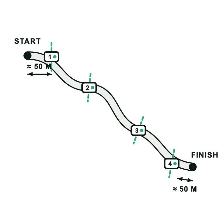
- At least two triggers: one about 50 m after the start point, one about 50 m before the stop point. Splits go in between — four triggers give start, two splits and finish.
- Closed lap
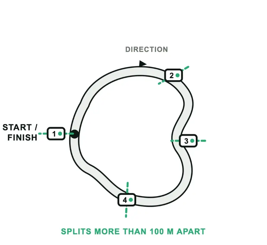
- One trigger at the start/finish line is enough — place it on a clear stretch, as far as possible from intersections, so a pass on another part of the loop cannot cross it. Add splits around the loop to break the lap down.
- Intermediate splits
- Extra triggers between the first and the last one, more than 100 m from each other. Declare the total number in use in the device configuration.
- Order
- Times are read in the order the triggers are crossed, so cross them along the track in that sequence — 1 first, then 2, 3 and 4 — and keep the same layout between runs if you want to compare splits.
Riders, vehicles and setups
Rider, vehicle, device
All setup data is stored in the software. The unit itself holds only the name of the vehicle it is fitted to, plus the few values it needs while recording. Note that three separate things in the system are called a profile — the rest of this chapter assumes you can tell them apart:
- Profile (user profile)
- Who is riding — name, date of birth, weight and height. Runs and the Garage are filed under it. One profile is active at a time; switch it from the profile switcher on the Home page.
- Vehicle, in the Garage
- One vehicle — brand, model, configuration, year, geometry and its setup history. Created in the app or PC software; vehicles are not stored in the unit.
- Profile, in device configuration
- The profile and vehicle names the unit writes into every run. They are what lets a downloaded run match itself to the right profile and vehicle.
Vehicle and rider configuration
Create the vehicle in the Garage with "+ Add vehicle". Brand and model are mandatory: the unit carries the name they make into every run, and the software matches that name back to this vehicle. Then enter the geometry the software needs to turn sensor movement into suspension travel, and the leverage ratio for each wheel.
- In the Garage, select the vehicle you are about to ride.A green readiness dot means the required geometry is complete. Amber means a value is missing and the run will not load, asking you to fill in the missing details every time.
- Connect to the unit over Wi-Fi.Hold the run button for 2 seconds to enable connection mode, then join the BYB-DeviceName network from your phone or computer.
- In the device panel, open Profiles, select the profile and use "Load from Garage…" to send the configuration to the unit.The unit stores one configuration at a time: the last one sent.
- Ride. Every run recorded from now on carries that vehicle name, and is matched to the vehicle automatically when you download it.
| Field | Unit | Example |
|---|---|---|
| Suspension travel | mm | 200 |
| Sensor travel | mm | 210 |
| Wheel travel | mm | 215 |
| Wheel size | in or mm | 29 · 690 |
These values live with the vehicle in the Garage and are edited there. They change rarely — only when a part is changed. A vehicle with more suspensions has one field for each suspension.
Setup history
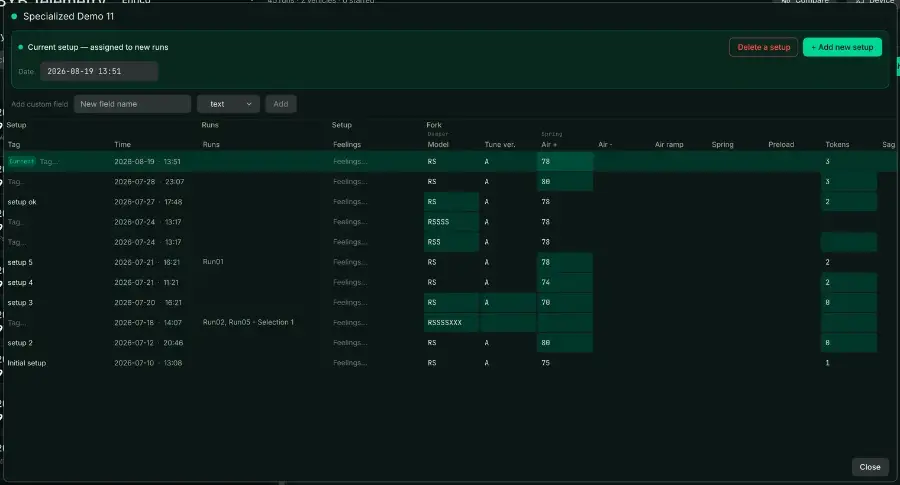
Everything you adjust between runs belongs to the setup. Adjust the vehicle, save the setup in the Garage, then ride: each save adds a dated setup to that vehicle. The history builds itself — there is no separate log to keep. When you download a run, the latest setup line is assigned to it automatically.
| What | Where it lives | How often it changes |
|---|---|---|
| Geometry — suspension travel, sensor travel, wheel travel, wheel size | With the vehicle in the Garage | Rarely, when a part is changed |
| Tune — clickers, pressures, spring, tyre, custom fields | A dated setup in the vehicle's setup sheet | Every session, freely |
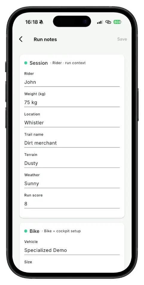
| What happened on this run — rider, location, remarks | The run's own notes | Per run |
How runs find their vehicle
Runs are matched by name, then by date. As each run is imported, the rider name it carries sends it to a rider profile, the device profile name matches it to a vehicle in the Garage, and the recording time selects the setup that was current at that moment. The run then keeps its own copy of that setup.
Importing never gets in your way:
- It never stops to ask you a question — every run is imported.
- A run whose rider is unknown goes into the Guest profile, and you can move it to the right rider later.
- A run whose name matches no vehicle is imported without one. No vehicle is created for it.
- Renaming a vehicle keeps the old name as an alias, so recordings that still carry it keep matching.
When you change something mid-session
You moved a clicker between runs and typed it into the run notes/setup. On save, the software asks what that change means, because only you know. Three options:
- Log it as a new setup
- A new setup is added, dated at the start of this run, and this run is tied to it. Every later run uses it too.
- Update the current setup
- The vehicle did not change — the saved setup was wrong: a mistyped clicker, a value never filled in. It is corrected in place, with no new entry and no new date. Offered only when the run follows a saved setup.
- Only this run
- A one-off change that you undid afterwards. The run is marked "Custom" and the setup history is left alone, but the link to the vehicle stays, so the run still appears in that vehicle's filters and trends.
Fixing a run afterwards
Nothing repairs itself, by design — the corrections are yours to make, and they are all in the run row or the run notes.
| Problem | Fix |
|---|---|
| Wrong or missing vehicle | Run row, "Assign vehicle…". Several at once: select the runs, then "Assign vehicle". |
| Wrong setup | Run row, "Assign specific setup…", then pick from that vehicle's setups, newest first. It overwrites the run's own copy of the values. |
| The run predates every setup | Correct the history, not the run: edit the date of the setup, or add a new one, then assign it. |
| There genuinely was no setup | "No setup for this run". The run stops asking. |
| A change was never written down | Add the setup by hand, dated when the change was made, so the history has no gap. |
Download runs and manage configurations
Getting the data off the unit, from the desk or the pits.
The Device panel
The app and the PC software show the same Device panel and do the same job: they list what is stored on the unit and pull it onto your phone or computer.
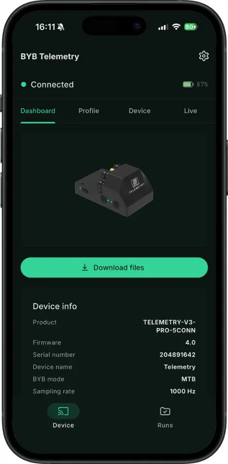
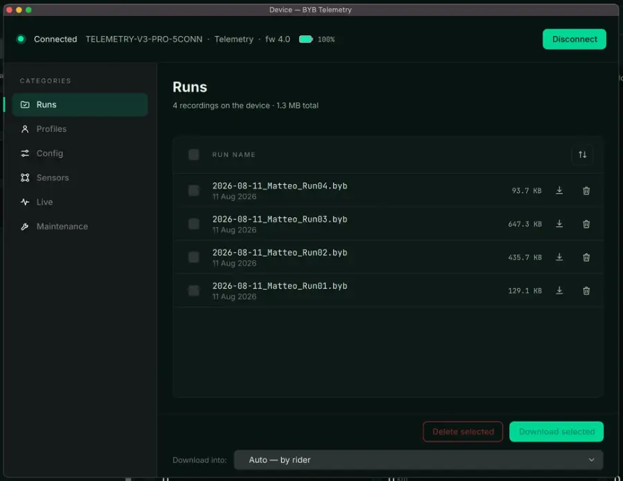
- Connect to the unit over Wi-Fi.Hold the run button for 2 seconds to enable connection mode, then join the BYB-DeviceName network from your phone or computer.
- Open the app or the software.
- Open the Device panel — the app opens on it, in the software it is the Device button in the top bar.
- Check the header: it names the unit, its firmware and its battery level.
- Download the runs.In the app, tap Download files.In the software, tick the runs you want and press Download selected. The "Download into" setting decides the folder — leave it on Auto and runs are filed by rider.
- Use the other categories — Profiles, Config, Sensors — to manage the unit, then press Apply.
This manual covers capturing the data and filing it under the right vehicle. Reading it — channels, charts, run comparison and trends — is the software and app manual, and what it means for a setup is the online training course at bybtech.it.
Firmware update
Two minutes, on the charger.
Updating the firmware
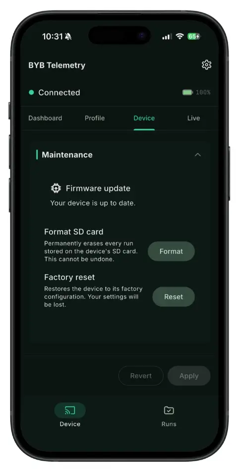
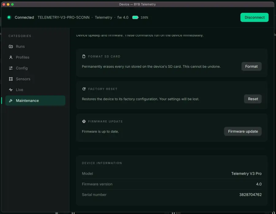
- Connect to the unit over Wi-Fi.Hold the run button for 2 seconds to enable connection mode, then join the BYB-DeviceName network from your phone or computer.
- Open the app.
- If a new firmware version is available, a pop-up appears.
- Follow the on-screen instructions to complete the update.
Charging the system
Internal rechargeable battery, 5 V 1 A.
Battery charging
- Remove the micro USB protective cap.
- Connect the micro USB cable to the port on the unit.
- Use only a PC USB port or a phone charger rated 5 V, 1 A.
- The charging LED is on while charging and off when the battery is full.
- Refit the protective cap before the next ride.
Cleaning the system
It is a professional instrument. Treat it like one.
System cleaning
Clean BYB Telemetry gently, with water and a soft cloth.
Troubleshooting
Find the symptom, apply the fix. Anything not here: info@bybtech.it.
The unit will not get a GPS fix
Switch the unit on a few minutes before the first run and leave it still, with the antenna in the open and a clear view of the sky. A fix normally takes about 5 minutes from cold. The run LED turns solid green when a reliable 3D fix is acquired.
If it still will not fix:
- Check the antenna cable is fully seated in the SMA connector.
- Move the antenna higher and away from metal, carbon and bodywork that shadow the sky.
- Move away from buildings, trees, awnings and paddock structures.
The run has no GPS map
Data logging started before a fix was acquired, so the run holds sensor data but no position. Always wait for the run LED to turn solid green before you press run — red means the GPS is still searching.
The unit is not responding
Hold the power button for about 15 seconds. The unit restarts on its own; nothing recorded is lost.
The Wi-Fi password is not accepted
- Try the default password: bybtelemetry.
- If the password was changed and cannot be remembered, hold the power button for 8 seconds to factory reset the unit, then connect again with the default password.
The unit does not appear in the Wi-Fi list
- Hold the run button for 2 seconds to enable connection mode — the run LED blinks fast blue when it is active.
- Look for BYB- followed by the device name, not BYB-Telemetry, if the unit was renamed.
- Turn mobile data off, or tell the phone to stay on this network: with no internet, phones often drop the connection on their own.
- Charge the unit — a red power LED means the battery is below 40%.
A channel reads zero or a flat line
- Check the connector is fully seated and the cap is off the channel in use.
- Check the selected mode matches the vehicle and the sensors you have connected — see Using the unit.
- Check the sensor cable for a pinch or a pulled connector at the sensor end.
- Swap the sensor to another channel: if the fault follows the sensor, the sensor is at fault; if it stays with the channel, the unit is.
On a unit with user-defined channels:
- Check each channel is mapped to the sensor actually plugged into it.
- Check the mapping was sent to the unit before the session — it cannot be changed afterwards.
The suspension data looks wrong or clipped
A trace that never reaches full travel, or that flattens at the top or bottom, is nearly always calibration or fitment rather than a fault.
- Recalibrate: manual calibration must be repeated every time a sensor or a mounting is moved or refitted.
- Check the travel values entered for the vehicle match the suspension actually fitted.
- Check the sensor stroke covers the full travel of the suspension — see Kit configurations.
- Check the mountings are not moving: a bracket that shifts under load flattens or distorts the trace.
- Check the sensor is not bottoming out before the suspension does, and that the joints are aligned so nothing binds.
A run is missing, or the software will not load it
- Check the mandatory vehicle parameters are filled in — without them the software cannot load the run, and asks for the missing details every time.
- Check the run was stopped with the run button before the unit was switched off.
- Check the auto pause settings: with a minimum speed set, a session spent stationary records nothing.
- Reconnect and refresh the device panel — see The Device panel.
No brake or speed signal
V3 Pro only- Check the gap between magnet and sensor end — a few millimetres, no more.
- Check the south pole of the magnet faces the end of the sensor, and that neither has moved.
- Check the channel mapping matches where the sensors are plugged in.
The battery does not last a session
- Check the charge LED went off before you unplugged: it stays lit until the battery is full — see Charging the system.
- Check the charger rating and charge time against Specifications.
Specifications
Acquisition and memory
| V3 | V3 Pro | |
|---|---|---|
| Sampling rate, each channel | 500 Hz | 500 – 1000 Hz |
| Internal memory | 2 GB | 4 GB |
| Battery life, sampling | 8 h + | 10 h + |
| Battery life, sleep | 250 days | 300 days |
| Charge time | 2.5 h | 3 h |
| Weight | 75 g | 80 g |
| Value | |
|---|---|
| Accuracy | 1% |
| Accelerometer | 3-axis, ±16 g |
| Gyroscope | 3-axis, ±1000 °/s |
| GPS | Automotive-grade module, 25 Hz multi-constellation, ±0.5 m, external high-sensitivity antenna |
| Dimensions | 80 × 50 × 40 mm |
| Material | Plastic |
| Charging connector | Micro USB, 5 V 1 A |
| Sensor connector type | 5-pin female |
| Water resistance | Acquisition unit and sensors IP65, connectors IP67; micro USB port not sealed |
| Mounting brackets | One pair included |